
Anyone can learn to read architectural drawings. The key is knowing where to look first: start with the title block, confirm the scale, read the legend, and locate the sheet index. Those four steps unlock every drawing set you will ever encounter, whether you are a trainee quantity surveyor, a small builder, or an architect's client trying to understand what is being built.
Before you read a single wall line, run this quick-start checklist:
- Check the title block (bottom-right corner of most sheets): project name, drawing number, scale, issue date, and revision letter.
- Confirm the scale using the graphic scale bar printed on the sheet, not a ruler against a PDF printout.
- Read the legend and symbol list on the cover sheet or general notes sheet before interpreting any line or hatch.
- Locate the sheet index on the cover sheet so you know which sheets exist and how they are organised by discipline.
Pro Tip: When you open a new drawing set for the first time, spend five minutes on the cover sheet alone. The sheet index, general notes, and legend will answer most of the questions that would otherwise send you hunting across dozens of sheets.
Standards such as NRM2 govern how quantities are measured from drawings in the UK, and BIM (Building Information Modelling) is increasingly how those drawings are authored. Tools like Quantiflow automate the measurement step, but professional judgement still starts with being able to read the drawings yourself.
Key takeaways
Reading architectural drawings accurately is the foundation of every reliable quantity takeoff, cost estimate, and site instruction, and it is a skill built through deliberate, structured practice rather than passive familiarity.
| Point | Details |
|---|---|
| Start with the title block | Check issue state, revision letter, and scale on every sheet before reading anything else. |
| Written dimensions always win | Never scale off a PDF; use the graphic scale bar to verify print accuracy first. |
| Follow the one-room chain | Trace one room across plan, elevation, section, schedule, and spec to build reading fluency fast. |
| Log every RFI | Document all drawing conflicts and ambiguities in writing before work or ordering begins. |
| Quantiflow for measurement | Once drawings are readable, Quantiflow automates NRM2-aligned takeoffs from PDF sets with a full audit trail. |
Table of Contents
- What do architectural drawings actually communicate?
- The main drawing types and views in a set
- Key drawing conventions: title block, legends, scales, and line types
- How to read a floor plan step by step
- How to read elevations and sections
- Reading construction details, schedules, and specifications
- A quick guide to structural, MEP, and civil sheets
- Common beginner mistakes and a pre-construction checklist
- Practical ways to study and practise reading drawings
- Why accurate plan reading matters for quantity takeoffs
- What field experience teaches you about reading plans
- Automating measurement once you can read the drawings
- Sources
What do architectural drawings actually communicate?
Drawings translate a three-dimensional building into a coordinated set of two-dimensional instructions. Every sheet in a set is a view of the same building from a different angle or at a different level of detail. What drawings do NOT do is tell you exactly which product to use, what performance standard to meet, or how a contractor should sequence the work. That information lives in the specifications.
The distinction matters in practice. A floor plan shows you that a wall is 150 mm thick and has a door opening. The specification tells you the wall is a 100 mm metal stud partition with two layers of 15 mm fire-rated plasterboard on each face, achieving a 60-minute fire rating. Miss the spec, and you might price or build the wrong wall entirely.
| Dimension | Drawings | Specifications |
|---|---|---|
| What they show | Geometry, location, and relationships | Materials, performance, and workmanship |
| Who uses them most | Builders, surveyors, site managers | Contractors, procurement teams, inspectors |
| Where they live | Numbered sheets (A-101, S-201, etc.) | Separate document, often NBS or CSI format |
| What they control | Layout, dimensions, and assembly sequence | Product standards, tolerances, and testing |
| What happens when they conflict | Issue an RFI and pause the affected work | Specification typically takes precedence |
As Carnegie Mellon University's construction planning resource explains, the real skill is linking drawings to real-world control points and coordinating them with construction documents, not reading either in isolation.
The main drawing types and views in a set
A full drawing set is a coordinated collection of sheets, and the cover sheet and legend are the essential starting points for decoding everything else. Each sheet type answers a specific question about the building.
The seven core drawing types:
- Site plan: Shows the building's position on the plot, boundary lines, access roads, drainage runs, and orientation. Answers: where does the building sit?
- Floor plan: A horizontal cut through the building at roughly 1,200 mm above floor level, showing walls, openings, room names, and dimensions. Answers: what is the layout of each floor?
- Elevation: An orthographic (flat, undistorted) external view of each facade. Answers: what does the outside look like and how tall is it?
- Section: A vertical cut through the building showing floor-to-floor heights, roof build-up, insulation, and foundation depth. Answers: how is the building assembled from top to bottom?
- Detail drawing: A large-scale close-up of a specific junction or assembly (e.g., a window cill, a parapet, a stair nosing). Answers: exactly how is this connection built?
- Reflected ceiling plan (RCP): A floor plan viewed as if looking up at the ceiling, showing light fittings, diffusers, sprinkler heads, and ceiling grid. Answers: what is on the ceiling and where?
- Schedules: Tabular sheets listing doors, windows, finishes, or room data. Answers: what are the exact specifications for each tagged element?
Sheet numbering follows a consistent pattern across most practices. Architectural sheets typically begin with A (A-101 for the ground floor plan, A-201 for elevations), structural sheets with S (S-301 for a typical framing plan), and MEP sheets with M, E, or P respectively. Civil sheets often carry C. Knowing this lets you jump directly to the right discipline without scrolling through the entire set.
Key drawing conventions: title block, legends, scales, and line types
Every drawing set follows conventions that, once learned, make any set readable regardless of who drew it. The title block is the first thing to check before interpreting a single line.
What the title block tells you
The title block, usually in the bottom-right corner, contains:
- Project name and address
- Drawing title and number (e.g., "Ground Floor Plan — A-101")
- Scale (e.g., 1:50 or 1:100)
- Issue date and revision letter/number
- Issue state (e.g., "For Construction", "For Tender", "Preliminary")
- Designer's name, firm, and professional seal
- Revision index listing all previous revisions and their dates
The issue state is critical. A sheet marked "For Information" or "Preliminary" should never be used to order materials or set out a building.
Legends and symbols
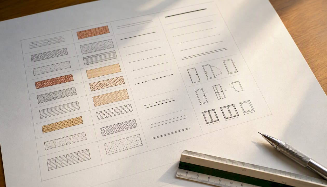
Legends decode the hatches, line types, and symbols used throughout a set. Architectural legends typically show wall types (solid hatch for masonry, hollow for timber stud), door and window symbols, and material hatches. Structural legends show rebar notation and connection symbols. MEP legends show duct, pipe, and circuit symbols. Each discipline has its own legend, usually on the first sheet of that discipline's section.
Scales and why written dimensions always win
A scale of 1:50 means one unit on the drawing represents 50 units in reality. A graphic scale bar printed on the sheet remains accurate even if the sheet is printed at a non-standard size, which is why written dimensions take precedence over scaled measurements on any drawing. Never scale off a PDF unless you have confirmed the print scale is correct.
Pro Tip: Print a test sheet and measure the graphic scale bar with a ruler. If a 1-metre bar measures anything other than 20 mm on a 1:50 drawing, your print scale is wrong. Adjust the printer settings before taking any measurements.
Common line types and abbreviations you will encounter:
- Continuous thick line: visible edges and outlines
- Dashed line: hidden elements below the cut plane (e.g., a beam above, a foundation below)
- Chain-dotted line: centre lines, grid lines
- AFF: Above Finished Floor (used for heights of fittings and fixtures)
- CLR: Clear (opening dimension, not the frame)
- T.O.S.: Top of Slab (structural datum reference)
- FFL: Finished Floor Level
Line weight (thickness) carries meaning too. Heavier lines indicate elements cut by the drawing's plane; lighter lines show elements beyond the cut. A wall cut in section is drawn thicker than a floor beyond it.
How to read a floor plan step by step
Floor plans carry the most information of any sheet type, and they are the anchor from which every other view is referenced. A structured approach prevents you from missing critical details.
- Orient yourself. Find the north arrow and confirm which floor level the plan represents (ground, first, basement). Check the floor level datum, usually expressed as a finished floor level (FFL) in metres above a benchmark.
- Read the walls. Wall thickness indicates construction type. A 300 mm+ wall is likely masonry; a 150 mm wall is often a stud partition. Cross-reference the wall legend to confirm the build-up.
- Identify openings. Door symbols show the leaf width and the direction of swing. Window symbols show the frame position within the wall. Both carry a tag (e.g., D-01, W-03) that links to the door or window schedule.
- Read the dimension strings. Most plans carry three layers: an overall dimension across the whole building, a running dimension between grid lines, and a detail dimension for individual openings. Always use the written dimension, never a scaled measurement.
- Follow the gridlines. Gridlines (labelled with numbers one way and letters the other) locate structural elements and allow you to coordinate the architectural plan with the structural and MEP drawings. A column on grid A/3 on the architectural plan should appear at the same grid intersection on the structural plan.
- Trace the callout bubbles. A circle with a number and a sheet reference (e.g., "3/A-401") means "see detail 3 on sheet A-401." Follow every callout that relates to an element you are measuring or building.
Pro Tip: When reading a floor plan for the first time, use a highlighter (physical or digital) to colour-code wall types. It takes two minutes and immediately reveals where partition types change, which is often where builders make costly errors.
Room tags typically show the room name, a room number, and the finished floor level. Some sets also include ceiling height in the room tag. If the ceiling height is not in the tag, check the RCP or the room data schedule.
How to read elevations and sections
Elevations and sections provide the vertical information that floor plans cannot. Together, they answer how tall the building is, how it is assembled, and where materials change.
Reading elevations
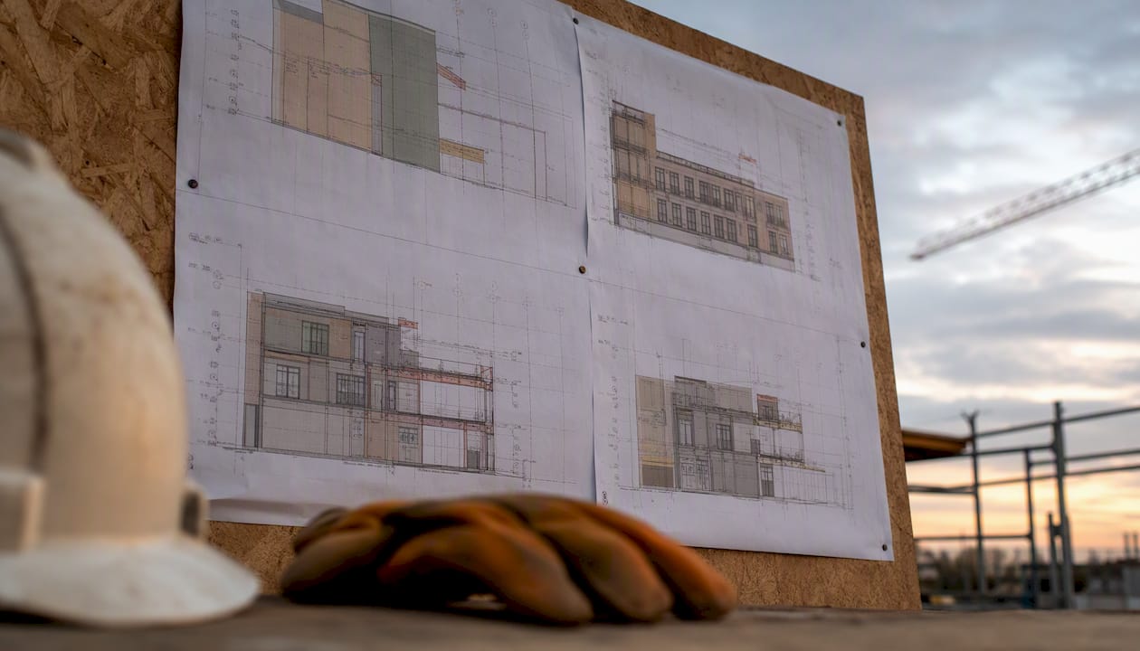
An elevation is a flat, orthographic view of one facade. It shows:
- External material zones and finish boundaries
- Window and door head and sill heights, usually expressed as dimensions from FFL
- Datum lines (e.g., FFL, top of parapet, ridge level)
- Material and finish notes, often with a keynote number that links to a schedule
To link an elevation back to the floor plan, find the elevation marker on the plan. It is usually an arrow or a circle with a letter (e.g., "Elevation A") pointing in the direction the elevation is looking. The sheet reference inside the marker tells you which sheet carries that elevation.
Public sample sets, such as those published by the City of San Rafael, illustrate how real-world elevations annotate material zones and datum lines, and they are free to download for practice.
Reading sections
A section is a vertical cut through the building. The cut line appears on the floor plan as a heavy chain-dotted line with arrows showing the direction of view. Follow these steps:
- Locate the section marker on the floor plan and note the sheet reference.
- Go to that sheet and confirm the cut direction matches the arrows on the plan.
- Read floor-to-floor heights from the dimension strings on the left or right margin.
- Identify the roof build-up, insulation layers, and any structural elements shown in the cut.
- Check foundation depth and any sub-floor void or drainage shown below FFL.
- Note any head heights for doors and windows that are not explicit on the elevation.
The elements shown in solid outline are those cut by the section plane. Elements shown in lighter line beyond the cut are visible but not cut through. This distinction matters when you are measuring areas or volumes from a section.
Reading construction details, schedules, and specifications
Details and schedules are where the precision lives. A floor plan tells you a door exists; the schedule tells you its exact size, material, fire rating, and ironmongery set; the detail tells you how the frame is fixed and sealed.
Detail drawings
Detail drawings are large-scale views (often 1:5 or 1:10) of specific junctions. A callout bubble on a plan or section, showing a number and a sheet reference, directs you to the correct detail. When reading a detail:
- Confirm the scale before measuring anything.
- Identify which elements are cut and which are shown beyond the cut.
- Read all keynotes and cross-reference them to the specification section they cite.
- Check whether the detail is "typical" (applies everywhere of that type) or specific to one location.
Door, window, and finish schedules
Schedules are tables. Each row represents one tagged element; each column records a property. A door schedule typically includes the door tag, leaf width and height, frame type, glazing requirement, fire rating, acoustic rating, hardware set, and finish. Always cross-check the tag on the plan against the schedule row before ordering or pricing.
Pro Tip: If a detail drawing and a specification clause appear to conflict, do not assume one is right. Issue a Request for Information (RFI) to the design team and wait for a written response before proceeding. Undocumented decisions made on site are the single most common source of rework disputes.
When drawings and specifications conflict
The specification typically takes precedence over the drawing for material and performance requirements. The drawing takes precedence for geometry and location. When both appear to conflict on the same point, the contract documents usually define a hierarchy. If they do not, raise an RFI. The RFI and submittal cycle exists precisely to document these decisions, creating an auditable trail that protects all parties.
A quick guide to structural, MEP, and civil sheets
Architectural sheets describe the building's form. The other disciplines describe how it stands up, how it breathes, and how it connects to the outside world.
Structural sheets (prefix S):
- Show gridlines, column positions, beam sizes, slab thicknesses, and rebar schedules.
- Foundation plans show pile caps, ground beams, and pad foundations.
- Key check: confirm that structural grid lines match the architectural grid exactly. Any discrepancy is a coordination error.
Mechanical, electrical, and plumbing sheets (M, E, P):
- Mechanical: ductwork routes, air handling unit locations, diffuser positions (cross-check with RCP).
- Electrical: circuit layouts, distribution board locations, lighting and power points (cross-check with RCP and room data schedules).
- Plumbing: pipe routes, drainage falls, fixture connections, and isolation valve positions.
Civil sheets (prefix C):
- Show site grading, finished ground levels, drainage runs, utility connections, and road layouts.
- Key check: confirm that finished ground levels on civil sheets match the FFL datum on architectural sheets.
Common coordination clashes to watch for:
- Structural beams conflicting with ductwork routes (the most frequent clash in commercial buildings).
- Sprinkler heads positioned where a light fitting is shown on the RCP.
- Drainage pipe slopes requiring a slab drop that is not shown on the architectural section.
- MEP service runs passing through structural walls or beams without a sleeve or penetration detail.
Cross-referencing between disciplines is not optional. A technical drawing checklist that covers discipline coordination is a practical tool for any site manager or surveyor working across a large set.
Common beginner mistakes and a pre-construction checklist
Most errors made when reading drawings are not failures of intelligence. They are failures of process. The same mistakes appear repeatedly on sites and in quantity takeoffs.
The most common beginner errors:
- Scaling dimensions off a PDF that has been printed at a reduced size.
- Ignoring revision clouds (the irregular bubble drawn around a change on a revised sheet).
- Using a superseded drawing issue (always check the revision letter in the title block).
- Skipping the schedules and assuming the plan contains all the information needed.
- Missing datum and tolerance notes, which can shift an entire floor level by 25 mm or more.
- Treating "typical" details as universal without checking whether exceptions are noted.
Pre-construction checklist:
- Confirm the issue state on every sheet you are working from ("For Construction" only).
- Verify the print scale using the graphic scale bar on at least three sheets from different disciplines.
- Cross-check every door and window tag on the plan against the corresponding schedule row.
- Confirm that architectural and structural grid lines align at every intersection.
- Locate the site benchmark and verify that all FFL datums trace back to it consistently.
- Check the revision index on each sheet and confirm you have the latest revision.
- Log any ambiguities or apparent conflicts as RFIs before work begins.
Pro Tip: When you receive a new drawing set, spend the first 15 minutes doing nothing but checking title blocks across every sheet. Note the issue state, revision letter, and date for each. Any sheet that is not "For Construction" or that carries a different revision from the rest of the set is a red flag to resolve before a single measurement is taken.
Document control is the discipline that keeps revision management reliable across large sets, and it is worth understanding early in your career.
Practical ways to study and practise reading drawings
Reading drawings is a skill, and skills are built through repetition, not passive reading. The most effective exercises follow one element through the entire drawing set rather than trying to absorb everything at once.
Exercises that build skill quickly:
- The one-room chain: Pick one room on a floor plan. Find it on the elevation, the section, the RCP, and the finish schedule. Note every dimension, material, and height that applies to that room. This single exercise teaches more than an hour of passive study.
- The door tag trail: Pick one door tag (e.g., D-07). Find it on the plan, locate it in the door schedule, find the frame detail, and read the relevant specification clause. Follow every cross-reference until there are no more to follow.
- The simple takeoff simulation: Choose one room and measure its floor area, wall area, and ceiling area from the drawings. Compare your figures against the dimensions stated on the plan and section. Any discrepancy reveals a reading error to investigate.
Recommended learning resources:
- The Coursera plan-reading and specifications course covers scales, symbols, discipline-specific sheets, and how specifications complement drawings, with hands-on exercises built into each module.
- Architecturecourses provides a step-by-step checklist and practice exercises structured around a beginner workflow.
- University open courseware (MIT OpenCourseWare, for example) includes construction document sets that can be downloaded and used for self-directed practice.
Digital tools for reading drawings:
- PDF viewers (Adobe Acrobat, Bluebeam Revu): allow annotation, measurement, and markup. Bluebeam is the industry standard on UK construction sites for a reason: its calibration and markup tools are built specifically for drawing review.
- CAD viewers (AutoCAD, DWG TrueView): allow you to read layer information, snap to geometry, and measure accurately. Understanding AutoCAD's layer and drawing setup conventions makes navigating CAD files significantly faster.
- BIM viewers (Autodesk Viewer, BIM 360, Navisworks): allow you to navigate a three-dimensional model, check clash detection results, and link model elements to their associated drawings and specifications. AutoCAD and Revit are the dominant authoring tools in UK architectural practice, so familiarity with their output formats is genuinely useful.
Pro Tip: When practising with PDF sets, use your viewer's annotation layer to mark up every callout you follow, every dimension you verify, and every RFI you would raise. Reviewing your own markup after a session reveals the gaps in your reading process far more clearly than any textbook exercise.
Why accurate plan reading matters for quantity takeoffs
Small reading errors compound quickly. A misread wall thickness, a missed floor level change, or an overlooked revision cloud can shift a Bill of Quantities by thousands of pounds on a modest project. The relationship between drawing accuracy and quantity measurement is direct: every measured item in an NRM2-aligned BoQ traces back to a dimension, a specification reference, and a drawing sheet number.
The workflow from drawing to takeoff follows a clear sequence:
- Locate the quantity item on the correct drawing sheet (e.g., external wall on A-101).
- Identify the measured dimensions from the written dimension strings, not scaled measurements.
- Cross-reference the specification to confirm the build-up and material standard.
- Check the schedule for any element-specific data (fire rating, finish, hardware).
- Record the assumption made at each step, including the sheet number and revision used.
Accurate plan reading is not just a technical skill. It is the foundation of every reliable cost estimate. A surveyor who cannot read drawings cannot measure them, and a measurement that cannot be traced back to a specific sheet and revision is not auditable.
That audit trail is where professional judgement becomes visible. Quantiflow automates the extraction and cross-referencing of measured quantities from PDF drawings, producing NRM2-aligned takeoffs with a traceable log of every dimension and assumption. It does not replace the surveyor's judgement on what to measure or how to classify it; it removes the repetitive manual work so that judgement can be applied where it matters. The relationship between AI assistance and professional judgement in quantity surveying is worth understanding before adopting any automated workflow.
Pro Tip: Keep a measurement log alongside every takeoff. Record the sheet number, revision letter, and any assumption you made for each measured item. If a drawing is revised later, you can identify exactly which quantities need to be rechecked rather than remeasuring the entire BoQ.
What field experience teaches you about reading plans
The gap between reading a drawing at a desk and understanding what it means on site is real, and it narrows only through deliberate practice. A few field-tested habits close it faster than any course.
Always verify control points before setting out. A gridline on a drawing is an abstraction; on site, it is a physical mark that must be established from a benchmark and checked against adjacent grids. Discrepancies between the drawing grid and the physical site are common, especially on refurbishment projects where existing structure rarely matches the as-built drawings.
Check for site conditions that could alter the layout. A structural beam at a height not shown on the architectural section, an existing drain run that conflicts with a new partition, or a floor level that varies from the FFL datum by more than tolerance. None of these appear on the drawings, but all of them require an RFI and a drawing revision before work proceeds.
For building your reading skills deliberately, this sequence works:
- Start with the one-room chain exercise on a simple residential floor plan.
- Repeat it on a more complex plan, adding MEP cross-checking (find the light fitting on the RCP, the circuit on the electrical plan, and the diffuser on the mechanical plan).
- Once that feels reliable, attempt a simple takeoff for one room, recording every assumption.
- Short daily sessions of 20–30 minutes beat occasional long ones. The habit of checking title blocks, confirming scales, and following callouts becomes automatic only through repetition.
Automating measurement once you can read the drawings
Once you can read a drawing set confidently, the repetitive work of extracting quantities from it is a strong candidate for automation. Quantiflow is built for exactly that stage: it takes PDF architectural drawings, extracts measured quantities using AI, cross-references them against specifications and schedules, and produces NRM2-aligned Bills of Quantities with a full audit trail.

The use cases where automation saves the most time are batch takeoffs across multiple rooms or floor levels, generating BoQ exports for tender in PDF or Excel, maintaining an auditable revision log when drawings are updated, and collaborating across quantity surveyor, builder, and architect roles on the same project. Quantiflow does not remove the need for professional judgement on classification, scope, or specification interpretation. It removes the manual counting and measuring that consumes hours on every project.
For practices working to NRM2 and looking to reduce the time between receiving a drawing set and issuing a priced BoQ, a free trial on the Quantiflow platform is a practical next step.
Sources
The resources below were used to build this guide and are worth bookmarking for deeper study.
- Plan reading and specifications — Coursera course
- Construction planning — Carnegie Mellon University CEE
- How to read construction drawings: a practical, field-tested guide — illustrarch
- How to read architectural plans for beginners — CLIMB