
Section quantities capture the vertical dimensions and build-ups a plan cannot show, while elevation quantities capture true face areas and heights for cladding, walls and openings. The immediate rule is simple: never derive a vertical measurement from a plan alone. Cross-reference the plan against the matching section and elevation, follow RICS NRM2 rounding and unit conventions, and record the sheet reference for every figure you take. Worked examples follow below.
TL;DR:
- Vertical measurements, such as face heights and build-ups, must be taken directly from sections, not plans, and cross-checked against the matching elevation.
- Formwork quantities are measured as contact areas between concrete and mold, calculated from section dimensions and recorded net as fixed in position per NRM2 rules.
- Elevation face areas should subtract openings, and a development factor must be applied for sloped surfaces, as plan measurements alone underestimate true surface areas.
- Accurate measurement requires verifying sheet revisions, cross-referencing views, recording references and assumptions, and rounding consistently according to NRM2 standards.
- Automated tools speed initial calculations but still require professional review, with Quantiflow offering a draft BoQ that preserves the surveyor’s judgment.
Table of Contents
- What do plans, sections and elevations actually show?
- Which NRM2 rules govern section and elevation takeoffs?
- What quantities come from sections and elevations, and how do you calculate them?
- How do you run a section and elevation takeoff step by step?
- Worked examples: formwork from a section, cladding from an elevation
- What quality checks should you run before sign-off?
- Where does software fit into a section and elevation takeoff?
- A draft BoQ that still needs your sign-off
- Sources
- FAQ
What do plans, sections and elevations actually show?
Each drawing type answers a different measurement question, and confusing them is where most takeoff errors start. A plan gives you runs, footprints and floor areas, usually at 1:100 or 1:50. An elevation gives you true face height and width for cladding, brickwork and glazing, typically at 1:100 or 1:50. A section cuts through the building to reveal floor-to-floor heights, structural depth and build-ups, often drawn at 1:50 or 1:20. Details zoom to 1:20 or 1:5 for junctions, thresholds and fixings.
The practical rule of thumb:
- Horizontal runs and floor areas: take from the plan
- Vertical heights, storey depths and structural build-ups: take from the section
- Face widths, face heights and fenestration positions: take from the elevation
Pointscan's guidance on reading general arrangement drawings confirms that sections reveal vertical relationships that plans simply don't carry. Always prefer figured dimensions over scaled ones, and note the sheet number and dimension string against every figure you record.
Which NRM2 rules govern section and elevation takeoffs?
RICS NRM2 sets the measurement conventions that make a Bill of Quantities professionally defensible, and several of them apply directly to work taken from sections and elevations.
- Net as fixed in position: NRM2 requires work to be measured net as fixed in position, which matters most for verticals and formwork, since it means you measure the finished element in place rather than an allowance for waste or lap.
- Rounding and unit presentation: figures should be rounded consistently within a work section, and items measured at less than one full unit still need to be stated and described clearly rather than omitted.
- Formwork measurement: NRM2 treats formwork as the contact area between concrete and the mould, not the finished concrete face, which is a distinction that trips up less experienced takeoff staff.
- Tabulated work sections: NRM2 organises measured items into trade-based tabulated sections, so a formwork or cladding quantity taken from a section drawing has a defined place in the bill structure, not a free-form entry.
Getting these conventions right early avoids rework further down the line. For a deeper walk-through of how the rules map onto everyday takeoffs, see NRM2 explained.
What quantities come from sections and elevations, and how do you calculate them?
Most of the line items surveyors pull from section and elevation drawings follow a handful of repeatable formulas. Get the logic right once and it applies across most projects.
- Formwork: measure the contact area between concrete and the mould, calculated as perimeter multiplied by height for a column or wall, and soffit area plus both sides for a beam. Take the height from the section, not the plan.
- Cladding and wall face areas: multiply face width by face height as shown on the elevation, then subtract the area of every opening within that face.
- Openings: measure door and window openings from the elevation, including reveal and trim allowances where the specification requires them, and deduct these from the gross face area rather than measuring them separately as a positive item unless the bill structure calls for it.
- Sloped and developed lengths: for pitched roofs, ramps and raked soffits, apply a slope or development factor to the plan length rather than using the horizontal run, because a flat plan measurement will always understate a sloped surface.
Exayard's guidance on measuring from drawings is blunt about this last point: a plan alone will understate sloped or vertical work every time, so developed length has to come off the section or elevation.
How do you run a section and elevation takeoff step by step?
A repeatable workflow protects you from the two most common failures: measuring the wrong sheet revision, and mixing scaled estimates with figured dimensions.
- Verify the sheet first. Check the revision number, issue date and drawing title before measuring anything, and recalibrate the scale on every individual sheet rather than assuming it matches the last one you opened.
- Follow the cross-reference sequence. Work from plan to elevation to section to detail, checking that the same element lines up across all three views before you commit a figure.
- Record the trail as you go. Log the sheet reference, the exact dimension string used, and any assumption you had to make, against every quantity you enter.
- Apply NRM2 rounding. Round consistently within each work section and flag provisional allowances explicitly where the drawing set leaves a detail unresolved.
Exayard's quantity takeoff guidance makes the same point about scale recalibration: treat figured dimensions and the drawing schedule as authoritative, and only fall back on scaling when no figured dimension exists. For the mechanics of measuring PDF sheets specifically, how to measure PDF drawings for NRM2 takeoffs walks through the calibration step in more detail.
Pro Tip: Where a drawing set is incomplete or the revisions don't quite agree with each other, don't guess. Add a provisional item, state the assumption in plain language against that line, and move on. It's far easier to resolve a flagged assumption at tender stage than to defend an unexplained figure after the contract is signed.
Worked examples: formwork from a section, cladding from an elevation
Example 1: Beam formwork. A section shows a beam 300mm deep and 250mm wide, spanning 4.2m, taken from drawing S-102 revision C. Soffit contact area is 4.2m × 0.25m = 1.05m². Each side is 4.2m × 0.30m = 1.26m², so both sides total 2.52m². Combined contact area is 3.57m², recorded net as fixed in position per NRM2's formwork rule.
- Sheet reference: S-102 Rev C
- Dimension string: 4.2 × 0.25 (soffit) + 2 × (4.2 × 0.30) (sides)
- NRM2 rule applied: formwork measured as contact area, not concrete volume
Example 2: Elevation cladding. Elevation E-04 shows a cladding face 12.6m wide by 3.4m high, giving a gross area of 42.84m². Two window openings of 1.8m × 1.5m each remove 5.4m² combined, leaving a net cladding area of 37.44m², rounded to 37.5m² per the project's rounding convention. No slope factor applies here since the face is vertical, but a raked gable end on the same elevation would need a development factor before the area is finalised.
What quality checks should you run before sign-off?
A short QC pass before a bill goes out catches most of the disputes that would otherwise surface at tender or valuation stage.
- Reconcile totals across views. Sum areas independently from the plan and from the elevation or section, and investigate any variance rather than averaging it away.
- Re-check scales on suspect sheets. If a figure looks out of step with the rest of the set, recalibrate that sheet's scale before assuming the drawing is wrong.
- Keep a full audit trail. Sheet codes, dimension strings, assumptions and any waste allowance applied should all sit against the quantity they support, not in a separate note.
Pro Tip: Build the audit trail as you measure, not afterwards. Reconstructing which sheet a figure came from three weeks later, after a contractor query, costs far more time than logging it in the first pass. For a fuller checklist, see construction measurement quality control.
Where does software fit into a section and elevation takeoff?
Tools generally fall into three categories: manual CAD or PDF measuring software where you draw and calculate every quantity by hand, field apps for capturing dimensions on site, and automation platforms that attempt to extract quantities directly from drawing files. Automation can speed up the first pass on repetitive elements like standard openings or repeated bays, but manual professional checks remain essential wherever a drawing set is inconsistent or a junction is non-standard.
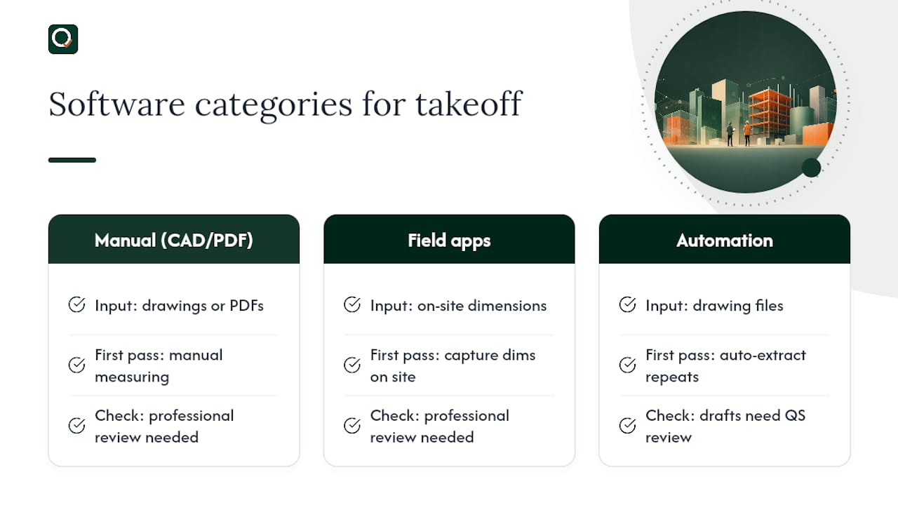
Some software tools read construction drawings and produce draft Bills of Quantities for quantity surveyors to review and sign off, but the review step remains essential. For a practical example of applying these principles to a specific trade, see concrete quantity takeoff: a practical guide for UK estimators.
A draft BoQ that still needs your sign-off
If you've followed the workflow above, you already know how much of a section and elevation takeoff comes down to disciplined cross-referencing rather than raw measuring speed. That's the gap Quantiflow is built to sit inside, not replace. It reads construction drawings and produces a draft Bill of Quantities for a quantity surveyor to review, adjust and sign off, keeping your professional judgement at the centre of every measured item rather than treating it as an afterthought.

It suits SME quantity surveyors, builders and architectural practices who want a structured starting point for a bill rather than a blank spreadsheet, particularly on projects with dense drawing sets where cross-referencing plan, section and elevation eats hours before you've priced a single item. Quantiflow is in development, with published plans including Solo and Business tiers, plus a custom Enterprise option for larger practices. If a draft starting point for your next section and elevation takeoff sounds useful, take a look at current plans and pricing and see which tier fits your workload.
Before any measurement is finalised, it's also worth checking who you're contracting with on-site. SzopaLabs' guidance on verifying a building contractor covers the practical checks worth running before a contract is signed, alongside your own measured quantities.
Sources
- NRM2: Detailed measurement for building works (RICS)
- Floor plans, elevations and sections explained (Pointscan)
- NRM 2 Detailed measurement for building works (RICS PDF)
FAQ
What Is the Difference Between Section and Elevation Quantities?
Section quantities cover vertical build-ups, structural depth and formwork contact areas taken from a cut-through drawing. Elevation quantities cover face widths, face heights and openings taken from an external view, and the two rarely substitute for each other reliably.
Can You Measure Height Directly From a Floor Plan?
No. A plan shows horizontal runs and footprints only, so heights, storey depths and sloped surfaces need to come from the matching section or elevation, as Exayard's measurement guidance sets out.
How Does NRM2 Define Formwork Measurement?
NRM2 measures formwork as the contact area between the concrete and the mould, not the volume of concrete itself, and requires it to be measured net as fixed in position.
Why Do Sloped Elements Need a Development Factor?
A plan records the horizontal projection of a sloped roof or ramp, which will always understate its true surface area. Applying a development factor from the section or elevation corrects for the slope before the quantity is finalised.
Does Quantiflow Replace the Quantity Surveyor's Takeoff?
No. Quantiflow reads construction drawings and produces a draft Bill of Quantities for a quantity surveyor to review and sign off, leaving professional judgement and final measurement decisions with the surveyor.
Recommended
- NRM2 explained: the RICS standard for measuring building works
- Audit Ready NRM2 Tiling Takeoff in 5 Steps for UK Quantity Surveyors
- NRM2 Ready 5 Step Structural Steel Takeoff for UK Estimators
- How to do a roofing takeoff from plans: NRM2 guide
This article is for general information only and is not professional, legal or commercial advice. Quantity surveying decisions should be taken by a qualified professional with reference to the specific project, drawings and contract in question. Content is produced with AI assistance and reviewed before publication. QuantiFlow Ltd accepts no liability for reliance on it.