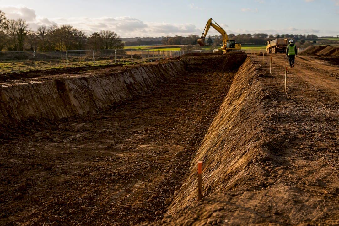
For a tender-ready cut and fill takeoff, use a TIN (surface-to-surface) model as your primary volume calculation, with cross-section or grid checks used to verify it, not replace it. TIN modelling triangulates existing and proposed survey data to compute volumes with far more geometric fidelity than hand methods on anything but the simplest sites. The workflow that gets you from drawings to a defensible Bill of Quantities line runs through data preparation, surface building, NRM 2-aligned coding, and a documented QA check before sign-off.
TL;DR:
- TIN modelling is the industry standard for complex or irregular sites, providing the highest accuracy in volume calculations compared to cross-section and grid methods.
- Data quality, including survey points, consistent coordinate systems, and proper layer naming, critically influences the reliability of cut and fill takeoff results.
- Proper documentation of assumptions, boundary definitions, and surface rebuilds helps prevent disputes and simplifies audit procedures later in the project.
- Conducting targeted hand-checks on complex site features and maintaining an audit trail of calculation decisions reduce rework and improve both accuracy and accountability.
- Using the NRM 2 standard correctly ensures consistent and comparable earthwork item descriptions, especially when approximations are necessary early in the design process.
Table of Contents
- What is a cut and fill takeoff and which method should you use?
- How do you build an audit-ready cut and fill workflow?
- How does NRM 2 apply to excavation and filling items?
- How do you convert bank, loose and compacted volumes?
- What data quality do you need for a reliable takeoff?
- What QA checks catch errors before sign-off?
- How does an audit-ready workflow support professional judgement?
- See how Quantiflow supports draft BoQ preparation
- Where to find the primary standards
- Sources
- FAQ
What is a cut and fill takeoff and which method should you use?
A cut and fill takeoff is the process of calculating how much material needs excavating (cut) and how much needs placing (fill) to bring a site from its existing ground level to the proposed design level. Three calculation methods dominate UK earthworks practice, and each has a legitimate place depending on the stage of design and the complexity of the terrain.
Cross-section (average end area) method. This is the oldest surviving technique and still the fastest for narrow, linear works such as roads, drainage runs, or cable trenches. You take a series of cross-sections at regular intervals along the centreline, calculate the cut or fill area at each section, average the area of two consecutive sections, and multiply by the distance between them. The formula is straightforward: Volume = ((A1 + A2) / 2) × L, where A1 and A2 are the end areas and L is the interval distance. It works well for consistent, corridor-shaped earthworks but loses accuracy fast on irregular or bowl-shaped sites, because it assumes a uniform transition between sections that rarely exists on complex ground.
Grid method. Here you overlay the site with a regular grid, typically 5 to 20 metres depending on how much the terrain varies, and take existing and proposed levels at each node. The difference at each node gives a cut or fill depth, and you average the four corner depths of each grid cell to calculate volume for that cell. Tighter grids (5 metres or less) suit undulating sites or areas with tight tolerances, such as car parks or sports pitches, while wider grids (15 to 20 metres) are usually adequate for large, gently sloping greenfield sites. The grid method is intuitive and easy to audit by eye, which makes it a favourite for spot-checking, but it can miss localised high or low points that fall between nodes unless the spacing is tight enough to capture them.
TIN or surface-to-surface method. Software builds a triangulated irregular network from every available survey point and breakline, creating two continuous 3D surfaces, existing and proposed, then calculates the volume of the solid trapped between them. Because a TIN uses every captured point rather than a sampled subset, it handles irregular terrain, retaining walls, kerb lines, and complex site geometries with a precision that grid and cross-section methods cannot match without an impractical amount of manual sampling. This is why TIN methods have become the industry standard for earthwork volumes on anything beyond the simplest linear works: modern grading software and drone-derived surfaces standardise the surface creation and volume reporting, though the output still needs a quantity surveyor to check it against contract boundaries and BoQ definitions before it goes into a tender document.
The practical trade-off is speed of verification against raw accuracy. TIN gives you the more accurate number for a detailed tender, but a grid or cross-section check remains the quickest way for a QS to sanity-check that number by hand, without opening a modelling package.
- Cross-section: best for roads, trenches, and other linear corridors with consistent geometry
- Grid: best for spot-checking and sites where node spacing can be tightened to match terrain complexity
- TIN: best for detailed, tender-ready takeoffs on irregular or complex sites, and the default recommendation for anything beyond a quick hand check
How do you build an audit-ready cut and fill workflow?
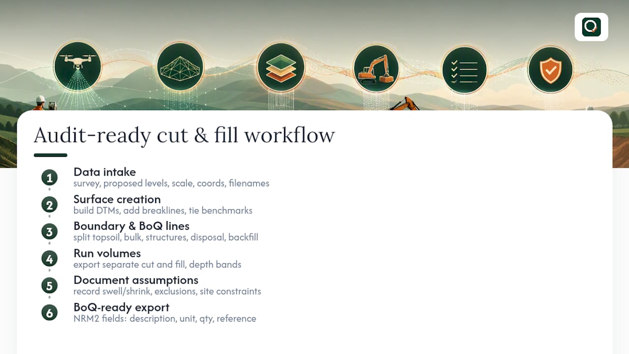
A defensible takeoff isn't just about picking the right calculation method. It's about building a chain of evidence that another QS, or a client's auditor, could pick up cold and follow from raw survey data to the final BoQ line. That chain has six practical stages.
1. Data intake and checklist. Before you open any software, confirm you have the deliverables you actually need: a topographical survey with spot heights and contours, the proposed levels design (often as a DTM or grading plan), drawing scales, the coordinate system in use (usually OSGB36 for UK projects), and consistent file naming across all drawing revisions. Mismatched coordinate systems between the existing survey and the proposed design are one of the most common causes of wildly wrong volumes, and they're invisible until you overlay the two surfaces and see the offset.
2. Surface creation. Build your existing and proposed ground surfaces from the survey points and design levels, adding breaklines along features that genuinely change grade, kerb lines, retaining wall tops, ditch inverts, so the triangulation doesn't smooth across a real change in level. Tie both surfaces to the same benchmarks. A frequent error here is triangulating across a watercourse or an existing structure that should be excluded from the earthworks surface entirely.
3. Work boundary and BoQ line drafting. Define the limits of the earthworks contract area against the site boundary and any retained features, then break the volume into the lines a BoQ actually needs: topsoil strip, bulk excavation, excavation for structures, disposal of surplus material, and imported or structural backfill. Getting this breakdown right at the drafting stage saves substantial rework later.
4. Running volumes. Generate separate cut and fill outputs rather than a single net figure, because a contractor pricing the works needs to know both numbers independently, along with depth bands where the specification calls for graded pricing (say, excavation in bands of 0 to 1 metre, 1 to 3 metres, and over 3 metres). Export these as tables ready to drop straight into your BoQ.
5. Documenting assumptions. Record every judgement call: the swell or shrink factors used, any areas excluded from the takeoff, and site constraints such as access restrictions that affect how material is handled. This record is what protects you when a figure is challenged months later.
6. Producing the BoQ-ready export. Structure the final export with the fields NRM 2 expects: a clear description, the unit of measurement, the quantity, and a reference back to the relevant NRM work section so a tenderer can see exactly what's included.
Pro Tip: Keep a single running spreadsheet of every assumption and exclusion as you go, not a memory of them reconstructed at the end. Six months on, when a contractor queries a bulk excavation figure, that log is the difference between a five-minute answer and a week of re-tracing your own steps.
The Calichi guidance on earthwork calculations makes a similar point: documenting topsoil depth, swell and shrink factors, and unsuitable material assumptions in a BoQ appendix heads off a large share of post-tender disputes before they start.
How does NRM 2 apply to excavation and filling items?
Earthworks sit within work section 5 of NRM 2: Rules for detailed measurement, excavating and filling, and the wording you use in the BoQ matters as much as the number you attach to it. NRM 2 sets out how items should be described and grouped so that tenderers price on a consistent basis, and departing from that structure is one of the fastest ways to generate confused or non-comparable returns.
Items normally measured under this section include:
- Topsoil stripping, usually kept separate from bulk excavation because it's often reused on site rather than disposed of
- Bulk excavation to reduce levels, measured net of topsoil once that's been stripped and coded separately
- Over-excavation, including working space required for structures or drainage, which needs its own line rather than being folded into bulk excavation
- Disposal of excavated material, distinguished between material retained on site and material removed off site
- Backfill and structural fill, split between general filling and filling that requires specified compaction or imported material
At early design stages, when the drawing information isn't detailed enough to measure with confidence, NRM 2 explicitly permits the use of approximate quantities with re-measurement on completion. If you're issuing earthworks quantities before the design has settled, flag them as approximate in the BoQ and note that final measurement will follow on completion against a schedule of rates. Leaving that qualification out is a common source of dispute when the as-built volumes diverge from the tender figure. It's worth reading the NRM2 explainer on how the standard structures BoQ items if you're newer to translating design drawings into NRM-compliant wording, particularly around how the excavating and filling section maps against the older SMM7 conventions many practices are still transitioning away from.
How do you convert bank, loose and compacted volumes?
A cut and fill volume calculated from survey data gives you the bank volume, the material as it sits undisturbed in the ground. Once excavated, that same material expands into loose volume because the excavation process introduces air voids, and once placed and compacted as fill, it settles into compacted volume, which is usually smaller than the bank volume it came from. Confusing these three figures is a quick route to a haulage estimate that's badly wrong.
- Swell describes the expansion from bank to loose volume, typically relevant when planning how many lorry loads a given cut will generate
- Shrink describes the reduction from bank (or loose) volume to compacted volume, relevant when working out how much fill material you actually need to bring in to achieve a design level
- Both factors vary by soil type and should come from a geotechnical report where one exists; where no geotechnical data is available, apply a conservative allowance and flag it clearly as an assumption rather than treating it as fact
Getting swell and shrink wrong is one of the more expensive mistakes in earthworks estimating, because it directly determines whether a site reads as balanced (cut and fill roughly matching) or as a net import or export of material, which changes the haulage cost picture significantly; that's why a well-planned construction contingency budget is essential to accommodate these cost impacts. Practical guidance on cut and fill calculations is consistent on this point: these conversions materially affect whether the earthworks balance, and skipping them produces a haulage figure that looks plausible on paper and wrong on site.
Topsoil stripping needs its own treatment in this conversion too. Decide early whether stripped topsoil will be stockpiled on site for reuse in landscaping or exported entirely, because that decision changes both the bulk excavation figure and the import requirement for structural fill. Record the assumed strip depth explicitly in a BoQ note or appendix, since a 150mm assumption instead of an actual 200mm strip depth across a large site adds up to a material quantity discrepancy fast.
What data quality do you need for a reliable takeoff?
The quality of a cut and fill takeoff is set almost entirely by the survey data feeding it, not the software used to process it. A few practical rules keep that data fit for purpose.
- Insist on spot heights and contours as a minimum, not just contours alone; contour-only surveys interpolate poorly across flat areas and can hide localised dips or humps that matter for drainage design. For anything with tight tolerances, an area survey or a drone-derived point cloud gives materially denser coverage than a traditional grid survey at a comparable cost.
- Match grid spacing to terrain variability. A gently sloping greenfield site can be checked confidently at 15 to 20 metre spacing; a site with retaining structures, mounding, or drainage swales needs 5 metres or tighter to avoid missing features between nodes.
- Standardise your export formats. CSV point lists for raw survey data, DWG or DXF for surface models, and Excel for volume tables cover most tender submission requirements and keep the takeoff auditable by a third party without specialist software.
- Name layers and files consistently, with revision numbers and dates baked into the filename. A takeoff built against superseded drawing revision C when the tender issued revision E is an error that's entirely preventable and depressingly common.
If you're routinely working from dense PDF drawing sets rather than native CAD files, it's worth reviewing how to extract reliable measurement data from PDF drawings before you commit to a grid spacing or survey density decision, since scale distortion in scanned PDFs is a frequent, quiet source of volume error.
What QA checks catch errors before sign-off?
The single most useful QA habit in earthworks takeoff is the sample hand-check: pick two or three representative cross-sections across the site, calculate the average end area volume by hand or in a spreadsheet, and compare that figure against what the TIN model reports for the same sections. A discrepancy beyond a small, agreed threshold should be investigated and documented before the quantity goes anywhere near a BoQ, not adjusted quietly and forgotten.
Beyond that reconciliation check, a handful of recurring pitfalls account for most of the rework and disputes seen on earthworks quantities:
- Work boundaries in the model don't match the contract drawing or site constraints plan, producing volumes for land outside the actual scope
- Topsoil has been omitted from the strip calculation, or an over-excavation allowance has been folded into bulk excavation instead of measured separately
- A late design revision changed proposed levels but the surface model wasn't rebuilt, so volumes are being calculated against a superseded design
- Layers are mislabelled or duplicated in the CAD file, causing the software to triangulate against the wrong surface
Keep a revision log every time a surface or boundary changes, and flag genuine unknowns, unconfirmed geotechnical conditions, or unresolved boundary disputes, to the client or tenderer rather than absorbing the risk silently into a single averaged figure.
Pro Tip: Run your hand-check cross-sections through the areas of the site with the most complex geometry, not the flattest. A discrepancy on a flat greenfield strip tells you very little; a discrepancy near a retaining wall or a drainage swale tells you whether your breaklines are actually doing their job.
How does an audit-ready workflow support professional judgement?
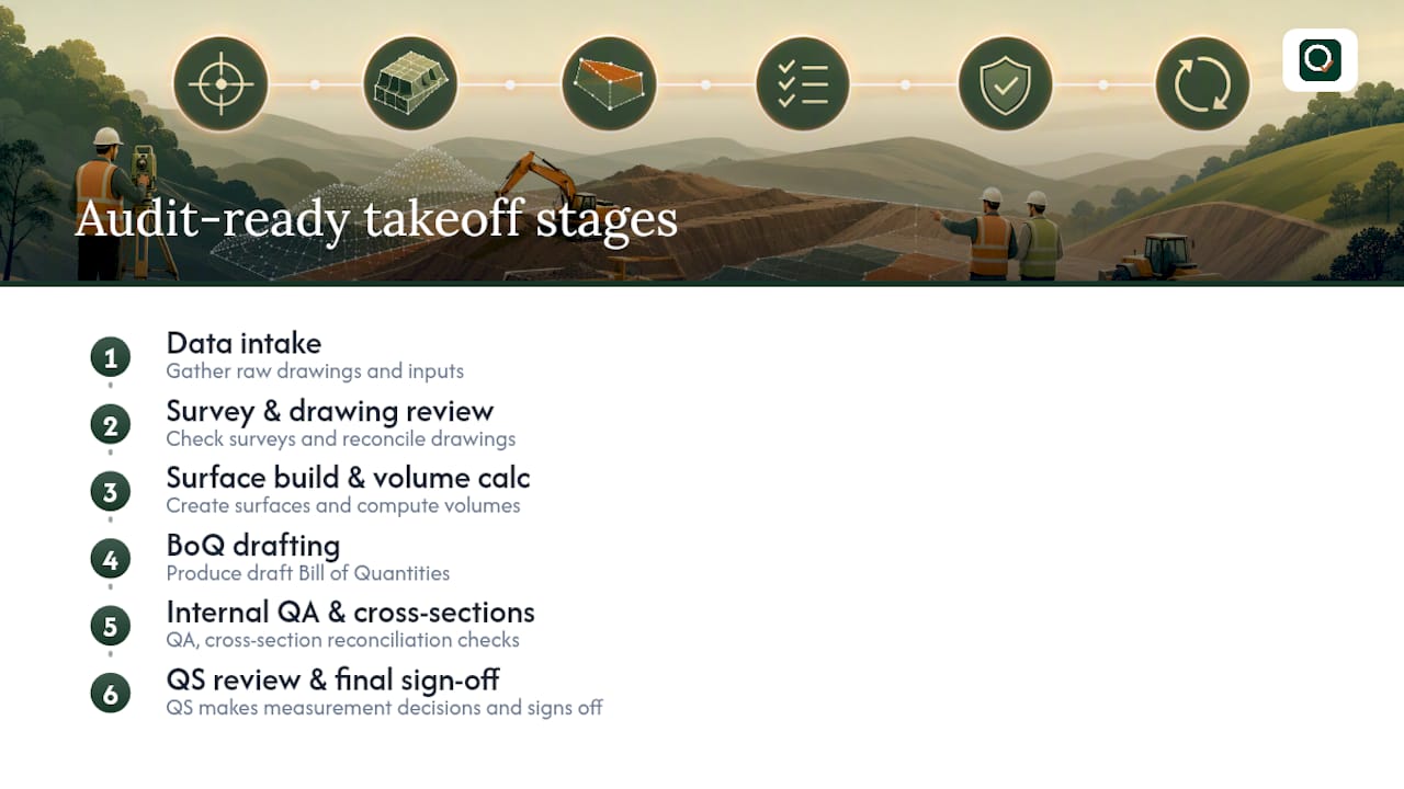
An audit-ready earthworks takeoff generally follows eight stages: data intake, survey and drawing review, surface build, volume calculation, BoQ drafting, internal QA and cross-section reconciliation, QS review, and final sign-off. Structuring the process this way gives every quantity a traceable path from raw drawing to priced BoQ line, which is what a client, contractor, or auditor expects to see when a figure is challenged.
Software has a real but bounded role in that chain. Quantiflow reads construction drawings and produces a draft Bill of Quantities for a quantity surveyor to review and sign off, a tool that speeds up the mechanical parts of surface building and quantity extraction without making the professional judgement calls that a QS makes: how to code an ambiguous item, whether a boundary assumption holds, or how to phrase a description so it survives tender scrutiny. Quantiflow is currently in development. Digital tools can supply draft outputs and an audit trail; they cannot supply the measurement decisions and sign-off that remain the quantity surveyor's responsibility, and no responsible workflow should present them as doing so.
See how Quantiflow supports draft BoQ preparation
If the workflow above sounds familiar, the tedious part usually isn't the methodology. It's the hours spent manually extracting quantities from dense PDF drawing sets before you can even start applying NRM 2 rules or running a QA check. Quantiflow reads construction drawings and produces a draft Bill of Quantities for a quantity surveyor to review and sign off, aimed at cutting down that manual extraction stage so your time goes into judgement and verification rather than transcription.

Quantiflow is in development, built around the same audit-trail principle covered above: every draft output is meant to be reviewed, adjusted, and signed off by a QS, not accepted as-is. A demonstration of the platform would typically show:
- A draft BoQ generated from an uploaded set of construction drawings
- The audit trail behind each draft quantity, so a reviewer can see how a figure was derived
- Export options into standard formats for use in tender documentation
Pricing is offered at multiple subscription levels, including Solo and Business tiers, with custom Enterprise terms available for larger practices. If you want to see how a draft BoQ workflow might sit alongside your own takeoff process, visit the Quantiflow product page to find out more.
Where to find the primary standards
For the definitive wording on measurement rules, consult NRM 2: Rules for detailed measurement directly rather than a summary. The comparison of SMM7 with NRM2 is a useful bridge for practitioners transitioning between the two standards.
Sources
- NRM 2 guidance on approximate quantities (RICS, Oct 2021)
- Cut and fill earthwork calculations explained (Calichi)
FAQ
How do I calculate cut and fill volume?
Build existing and proposed surfaces from survey and design data, then calculate the volume between them using a TIN model for accuracy, or a cross-section or grid method for a faster hand check.
What does "cut and fill" mean in earthworks?
Cut refers to material excavated to lower the ground to a design level, and fill refers to material placed to raise it, with the balance between the two determining whether a site needs imported or exported material.
How much does a cut and fill estimate cost?
Cost depends on survey density, site complexity, and whether the takeoff uses drone or LiDAR data versus a traditional ground survey, and no single industry-wide figure applies consistently enough to quote here.
How do you calculate cut and fill volume manually?
Use the average end area method: calculate the cross-sectional area at regular intervals, average each pair of consecutive sections, and multiply by the distance between them to get the volume for that segment.
Which cut and fill method is most accurate for a detailed tender?
TIN, or surface-to-surface modelling, is generally the most accurate method because it triangulates the full survey dataset rather than a sampled subset, though a sample cross-section check remains good practice before sign-off.
Recommended
- Eight Step Audit Ready Takeoff Workflow for Estimators
- Audit log best practices for UK quantity surveyors
- Audit Ready Electrical Takeoff for QSs: 5–15 Minute NRM2 QA
- Stop Bid-Stage Rework: Audit-Ready Finishes Quantity Takeoff for Estimators
This article is for general information only and is not professional, legal or commercial advice. Quantity surveying decisions should be taken by a qualified professional with reference to the specific project, drawings and contract in question. Content is produced with AI assistance and reviewed before publication. QuantiFlow Ltd accepts no liability for reliance on it.