
The symbols that actually matter for an accurate takeoff fall into four groups: electrical (outlets, fixtures, panels), HVAC (diffusers, dampers, GRDs), plumbing (fixtures, cleanouts, drains) and architectural or site symbols (doors, windows, finishes). Get those four right and you have covered most of what determines a defensible Bill of Quantities. The single best preparation rule, whether you are counting by eye or running an assisted takeoff tool, is this: prepare clear, high-contrast, precisely cropped symbol definitions before you count anything.
That sounds obvious until you have sat through a rework caused by a faded legend or a symbol crop with three millimetres of stray white space around it. Do this in the next five minutes:
- Open the drawing legend first and confirm every symbol used on the sheet is actually defined there.
- Check contrast: symbols should read clearly against the background line-work, not blend into it.
- Export or request vector formats (DWG, DXF, SVG) where possible rather than scanned raster PDFs.
- Crop any symbol definitions tight to the symbol itself, with no surrounding whitespace or stray annotation.
- Flag rotated, scaled, or mirrored variants of the same symbol before you start counting.
Industry guidance such as NECA 100 sets out standard electrical symbol presentation, while aviation-related takeoffs draw on AC 150/5340-18G for signage conventions. Tools like Quantiflow build symbol governance and pilot-scan auditing directly into the takeoff process, which is where most of this guide is heading.
Key Takeaways
A governed, high-contrast, precisely cropped symbol library is the single most reliable lever for accurate manual and automated quantity takeoffs.
| Point | Details |
|---|---|
| Check the legend first | Confirm every symbol on the sheet is defined before you start counting anything. |
| Prefer vector over raster | DWG, DXF, and SVG preserve geometry that raster scans blur at zoom. |
| Prioritise contrast | Symbols significantly darker than the background reduce misses in manual and automated review. |
| Crop precisely, every time | Remove stray whitespace and overlapping annotations from every symbol definition. |
| Run a pilot count first | Test symbol definitions on one representative area before scaling to a full project. |
| Map symbols to BoQ lines | Attach a counting rule and unit of measure to every symbol, not just a visual definition. |
| Consider a governed platform | Quantiflow maps imported symbol libraries to NRM2-aligned BoQ lines with a pilot-scan audit step. |
Table of Contents
- Which drawing symbols matter by trade
- How do you turn a symbol into a quantity?
- Preparing drawings for reliable automated symbol counts
- Building a symbol library your estimating team can actually trust
- A quick-reference cheat sheet for common takeoff symbols
- A workflow and troubleshooting checklist for symbol-based takeoffs
- Why a governed symbol library protects your margin
- How Quantiflow supports symbol-led takeoffs
- Sources
Which drawing symbols matter by trade
Not every mark on a drawing is a takeoff item. Some symbols exist purely to guide the reader through the design (arrows, cross-references, north points), while others represent something you must physically count, measure, or price. Learning to separate the two is the first real skill in reading construction drawings for quantity purposes, and it is worth revisiting the fundamentals in how drawings shape quantity measurement before you start on a live project.
Electrical. Outlets and switches are typically counted each; lighting fixtures follow the same rule but often need a fixture schedule cross-reference for wattage and type; distribution panels and switchgear usually get a lump-sum or schedule-based allowance rather than a simple count. Cable containment (conduit, trunking) is measured in linear metres, following the run rather than a point symbol.
HVAC. Supply and return air diffusers, grilles, registers, and dampers (GRDs) are almost always counted each, but the duct runs connecting them are measured linearly or by area depending on the specification. A single damper symbol might represent a £40 component or a £400 fire-rated assembly, so the symbol alone is never enough. Always cross-check the schedule.
Plumbing. Fixtures (WCs, basins, sinks) are counted each. Cleanouts and floor drains are counted each too, but pipework is measured in linear metres by size and material, which means the symbol only tells you where a pipe starts or terminates, not how much pipe exists.
Architectural and site. Doors and windows are counted each, generally cross-referenced against a schedule for size and type. Finishes (flooring, wall coverings) are measured by area, and their "symbol" is often a hatch pattern or a room tag rather than a discrete icon.
The practical distinction to hold onto: operational symbols route the reader through the drawing (north arrows, section markers, revision clouds) and never enter a Bill of Quantities. Quantity symbols represent a physical, priceable item, and those are the ones your takeoff process needs to detect reliably, whether by eye or by software.
How do you turn a symbol into a quantity?
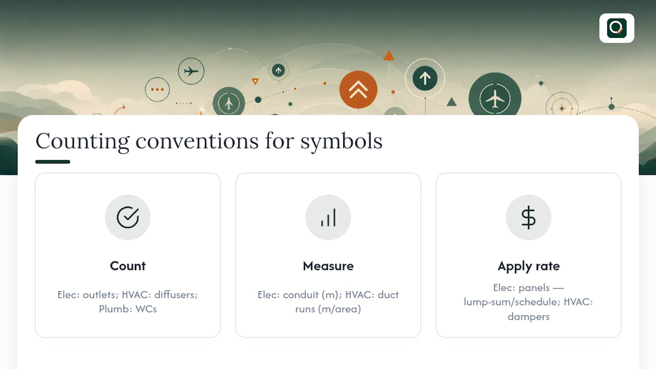
Every symbol on a drawing implies one of three counting conventions: count, measure, or apply a typical rate. Getting this wrong is one of the most common sources of pricing error, because a symbol that looks identical to another can carry a completely different measurement rule depending on context.
Count applies to discrete items with a fixed unit price: light fittings, sanitary fixtures, doors, access hatches. If you can point at one and say "that's one of them", it is a count item.
Measure applies where the symbol marks a route or boundary rather than a discrete object: cable runs, ductwork, pipework, skirting. The symbol tells you where the item starts and ends; you still need to trace its length or area.
Per typical or per area rules apply when a design repeats a configuration across multiple units, such as identical bathroom pods in a residential block. Rather than counting every fixture on every floor, you count one typical layout and multiply, which is a technique covered in more depth in this guide to setting out quantities for residential projects.
Some conventions vary by firm and by NRM2 code, so always confirm local practice before assuming a rule applies universally.
- Light fittings, sockets, sanitary ware, doors and ironmongery: count.
- Cable containment, pipework, ductwork, skirting and edge trim: measure (linear metres).
- Floor and wall finishes, roofing membranes, insulation: measure (area).
- Repeated identical layouts (typical flats, typical bathroom pods): count one typical, apply a multiplier.
Pro Tip: When a symbol looks ambiguous, ask whether removing one instance from the drawing would change the design. If yes, it is almost certainly a count item. If the drawing would still make sense with a slightly shorter or longer run, it is a measure item.
Preparing drawings for reliable automated symbol counts
Three preparation steps drive most of the accuracy gain when you move from manual counting to assisted or automated symbol detection: export vector formats wherever the drawing source allows it, increase contrast between symbol and background, and crop every symbol definition precisely, with zero stray whitespace or overlapping line-work.

Resolution and line-weight matter more than most estimators expect. A raster PDF scanned at low DPI will blur fine symbol detail, and a detection engine trained on a clean vector shape will miss variants that have softened at the edges. Vector formats (DWG, DXF, SVG) preserve exact geometry regardless of zoom level, which is why they consistently outperform scanned raster images for symbol matching. Layer discipline helps too: if electrical symbols sit on their own CAD layer separate from architectural background, both manual reviewers and detection software can isolate them far more reliably.
Colour usage deserves specific attention. NECA 100 guidance recommends that symbols be significantly darker than the surrounding background structure, a contrast principle that improves legibility for human reviewers and detection accuracy for automated tools in equal measure. A symbol drawn in a light grey line weight against a similarly light background is exactly the kind of thing that gets missed on a busy sheet, manually or otherwise.
Watch for these recurring failure modes:
- Extra whitespace in symbol crops. A crop with a wide margin around the symbol confuses pattern matching, because the software is now trying to match the whitespace too, not just the symbol.
- Overlapping annotations. Text labels or dimension lines crossing through a symbol distort its shape and reduce match confidence.
- Rotated or scaled variants. A damper symbol rotated ninety degrees, or drawn at a different scale on a mechanical schematic versus a plan, may not match the original definition unless the library accounts for both.
Pro Tip: Never crop a symbol definition from a single instance and assume it will generalise. Pull two or three examples of the same symbol from different areas of the drawing set first, then build the crop from the cleanest, most representative one. Running a pilot scan on one representative sheet before committing to a full-project run, an approach Autodesk's takeoff learning materials also recommend, catches most of these issues before they cost you a full re-run.
Building a symbol library your estimating team can actually trust
A reusable symbol library only earns its keep when it is governed, not just collected. The practical sequence runs in six steps: define the symbol, crop it precisely, name it consistently, tag it with metadata, test it against a sample drawing, then version it so future updates never silently overwrite the rules an old estimate relied on.
- Define the symbol's meaning against the project legend or the relevant standard (NECA 100 for electrical, for instance).
- Crop the symbol tightly, using two or three representative instances rather than a single lucky example.
- Name it using a consistent convention your whole team follows, not whatever felt intuitive on the day.
- Tag it with metadata: unit of measure, system group, and a reference to its source drawing.
- Test the definition against a pilot area before rolling it out across a full drawing set.
- Version the symbol so that updates are tracked and past estimates remain traceable to the definition that produced them.
A sample naming convention might run something like ELEC_OUTLET_DUPLEX_V2, where the trade prefix, item type, variant, and version number are all readable at a glance without opening the file. Symbol groups built this way map cleanly onto count sheets and BoQ line items, because the naming convention itself carries the classification logic.
| Attribute field | Purpose |
|---|---|
| Symbol ID | Unique reference for the symbol definition |
| Name | Human-readable, convention-based label |
| Unit of measure | Each, linear metre, or area, depending on item type |
| System group | Trade or system the symbol belongs to (electrical, HVAC, plumbing) |
| Sample count rule | Whether the item is counted, measured, or applied per typical |
| Reference source | The drawing or standard the definition was taken from |
Pro Tip: Never overwrite an existing symbol definition in place. Create a new version instead, and archive the old one against the estimates it produced. Practitioner accounts of symbol library management consistently point to this as the difference between a library that improves over time and one that quietly corrupts historic pricing data every time someone tweaks a crop.
A quick-reference cheat sheet for common takeoff symbols
Use this table during a live takeoff to map a symbol you are looking at directly to its counting rule and unit of measure, rather than guessing or re-deriving the rule from scratch each time.
For airside civils work, the FAA's quick reference guide sets out holding position signs and ILS critical area markings, and the FARAIM AIM chapter on airport signs gives the placement conventions behind them. Where you need a small annotated diagram for a cheat sheet or internal training document, keep it separate from your live symbol library; illustrative icon sets such as those found in general icon libraries are built for interfaces, not for standards-based construction drawings, and mixing the two invites confusion later.
A workflow and troubleshooting checklist for symbol-based takeoffs
The workflow that keeps a takeoff honest runs in a fixed order: prepare the drawings, confirm the legend, map every symbol to its count rule, run a pilot count on a representative area, audit the overlays against the original drawing, then finalise the full extraction.
- Prepare the drawings. Export vector where possible, check contrast, and confirm layer structure before anything else.
- Confirm the legend. Every symbol on the sheet should trace back to a definition; if it does not, stop and query the design team.
- Map symbols to takeoff items. Assign each symbol its counting convention (count, measure, per typical) and its BoQ code.
- Run a pilot count. Take one representative floor or zone and count it fully before scaling to the whole project.
- Audit overlays. Whether manual or automated, check the pilot results against the actual drawing for false positives and missed instances.
- Finalise. Only run the full extraction once the pilot has been checked and any symbol definitions corrected.
When counts look wrong, work through this list before assuming the drawing itself is at fault:
- Check contrast between the symbol and its background line-work.
- Look for layered text or dimension annotations crossing through the symbol.
- Check for rotated or scaled instances that may not match the library definition.
- Check for grouped entities, where several elements have been bundled into one block and are being read as a single item.
- Check for overlapping hatch patterns obscuring the symbol edge.
Pro Tip: Keep a running log of every symbol issue you catch during a pilot count, even the small ones. Feeding that log back into the symbol library, rather than fixing the same crop problem project after project, is what separates a governance process from a one-off workaround.
Why a governed symbol library protects your margin
The gap between an estimating team that treats symbols casually and one that governs them properly rarely shows up on the first project. It shows up on the third or fourth, when a symbol definition that was "close enough" the first time has quietly propagated errors through several bids without anyone noticing until a variance report flags a fixture count that doesn't match the drawing.
Poor symbol hygiene has a specific, predictable failure mode: a duplex receptacle symbol cropped with a stray dimension line through it gets missed on half the sheets in a set, the estimator notices the discrepancy late, and the whole electrical section gets re-run under deadline pressure. Governance prevents exactly this. A versioned library with tested definitions and a pilot-scan step catches the miscount on sheet one, not on the final audit before submission.
The business case for this is straightforward: faster bids, fewer reworks, and audit trails that hold up when a client or QS challenges a figure. That is not a technology argument so much as a discipline argument, and it applies whether your team counts by hand with a red pen or runs assisted detection across an entire drawing set. Software can enforce the discipline more consistently than a spreadsheet ever will, which is part of why platforms built specifically around preserving quantity surveyor judgement have gained traction with SME estimating teams rather than simply automating them out of the loop.
How Quantiflow supports symbol-led takeoffs
Quantiflow automates NRM2-aligned quantity extraction from PDF architectural drawings while keeping the quantity surveyor's professional judgement in charge at every key stage, which matters most exactly where symbol interpretation gets ambiguous.
The platform maps directly onto the pain points covered above. You can import a symbol library rather than rebuilding one from scratch on every project, and each symbol maps to a specific BoQ line so the count rule travels with the symbol rather than living in someone's memory. A pilot-scan overlay lets you audit auto-detected matches against the original drawing before committing to a full extraction, the same discipline recommended earlier for catching cropping and contrast errors before they cost you a rework. Every extraction is versioned and logged, so when a client queries a fixture count six weeks after submission, you can trace exactly which symbol definition produced it.
If your team is still resolving symbol ambiguity sheet by sheet, it is worth seeing how a structured extraction process handles it instead. You can explore Quantiflow's takeoff platform and start a trial to run your own pilot scan against a real drawing set.
Sources
Vector formats consistently beat raster for takeoff work: DWG and DXF preserve native CAD geometry, SVG works well for lightweight web-based symbol libraries, and layered PDF sits somewhere in between, useful when a client will only issue PDFs but the file retains selectable vector layers rather than a flat scan.
Native CAD blocks (DWG/DXF) remain the gold standard when the original design files are available, because every symbol instance retains its exact geometry, scale, and layer assignment. SVG is a strong choice for teams building browser-based or cross-platform symbol libraries, since it scales cleanly without quality loss. Layered PDF is the common fallback when only PDF issue is available, but it depends entirely on whether the originating CAD software exported genuine vector layers rather than flattening the drawing to an image, which is exactly the kind of technical setting worth checking against a resource like this technical drawing standards checklist before you commit to a workflow.
For authoritative symbol definitions rather than vendor-specific libraries, NECA 100 remains the standard reference for electrical construction drawing symbols, and aviation-related work should consult AC 150/5340-18G for sign and marking definitions.
- FAA — Airport sign and marking quick reference guide
- FARAIM — AIM, Chapter 2, Section 2.3.7 (Airport signs and markings)